
3D Printing Design Guidelines
Comprehensive design specifications for our manufacturing technologies. Follow these to ensure optimal print quality and avoid production issues.
FDM (Fused Deposition Modeling)
Layer-by-layer plastic extrusion technology
Min Wall Thickness (Unsupported)
1.2 mm
Min Wall Thickness (Supported)
0.8 mm
Min Feature Size
1.0 mm
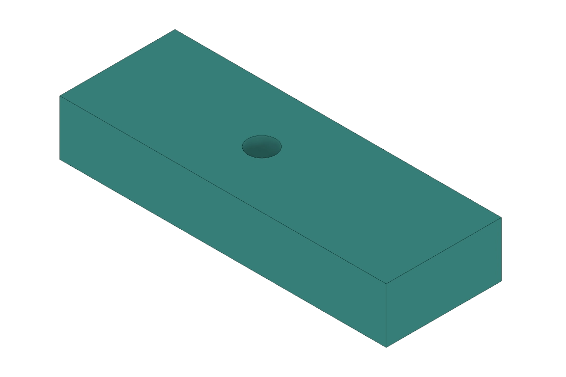
Min Hole Size
1.5 mm
Tolerances
±0.3 mm (±0.15 mm with post-processing)
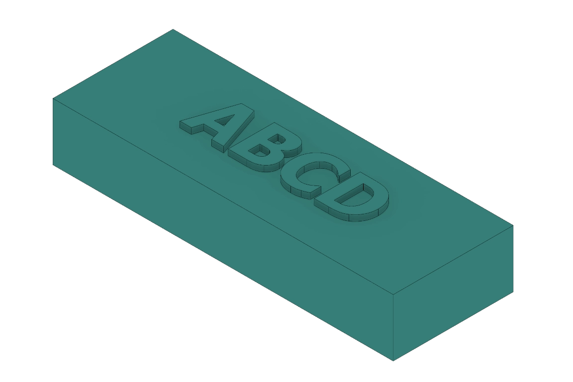
Min Letter Size
2.0 mm height, 0.6 mm depth
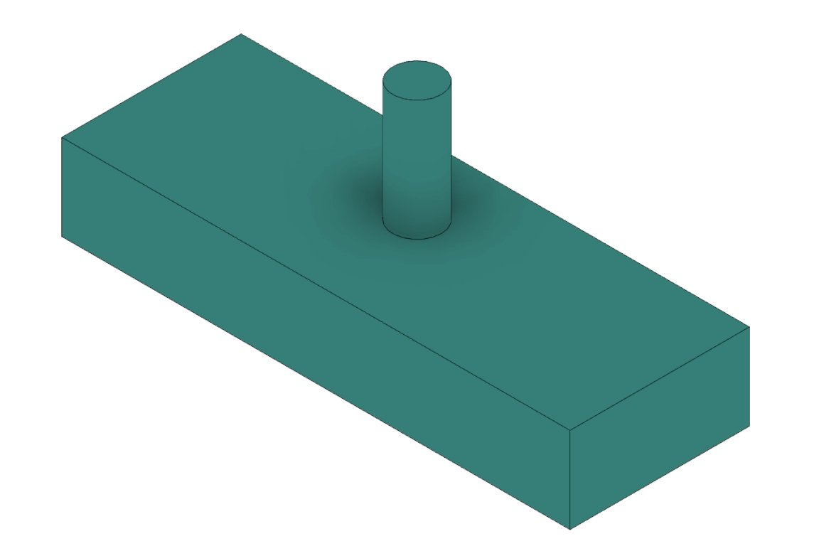
Min Pin Size
3.0 mm diameter

Max Overhang
45° without support
Layer Height
0.2 mm
SLA (Stereolithography)
UV light curing liquid resin technology
Min Wall Thickness (Unsupported)
0.8 mm
Min Wall Thickness (Supported)
0.5 mm
Min Feature Size
0.15 mm
Min Hole Size
0.5 mm
Tolerances
±0.1 mm
Min Letter Size
0.4 mm height, 0.2 mm depth
Min Pin Size
1.0 mm diameter
Max Overhang
19° without support
Layer Height
0.1 mm
SLS (Selective Laser Sintering)
Powder-based laser sintering technology
Min Wall Thickness (Unsupported)
1.2 mm
Min Wall Thickness (Supported)
0.8 mm
Min Feature Size
0.5 mm
Min Hole Size
1.0 mm
Tolerances
±0.15 mm
Min Letter Size
1.0 mm height, 0.3 mm depth
Min Pin Size
2.0 mm diameter
Max Overhang
No support required
Layer Height
0.12 mm
DLP (Digital Light Processing)
High detail UV light curing liquid resin technology
Min Wall Thickness (Unsupported)
1.2 mm
Min Wall Thickness (Supported)
0.8 mm
Min Feature Size
0.2 mm
Min Hole Size
0.5 mm
Tolerances
±0.1 mm
Min Letter Size
0.5 mm height, 0.2 mm depth
Min Pin Size
1.0 mm diameter
Max Overhang
35° without support
Layer Height
0.06 mm
PolyJet
Multi-material photopolymer jetting
Min Wall Thickness (Unsupported)
1.2 mm
Min Wall Thickness (Supported)
0.8 mm
Min Feature Size
0.1 mm
Min Hole Size
0.5 mm
Tolerances
±0.1 mm
Min Letter Size
0.3 mm height, 0.1 mm depth
Min Pin Size
1.5 mm diameter
Max Overhang
Support material available
Layer Height
0.016 mm
DMLS (Direct Metal Laser Sintering)
Metal powder laser fusion technology
Min Wall Thickness (Unsupported)
1.2 mm
Min Wall Thickness (Supported)
0.8 mm
Min Feature Size
0.2 mm
Min Hole Size
0.5 mm
Tolerances
±0.1 mm
Min Letter Size
0.5 mm height, 0.2 mm depth
Min Pin Size
1.0 mm diameter
Max Overhang
35° without support
Layer Height
0.06 mm
General Design Tips
- Design parts with consistent wall thickness when possible
- Avoid sharp internal corners - use fillets with minimum 0.5mm radius
- Consider the printing orientation to minimize support requirements
- Add draft angles (1-2°) to vertical walls for better surface finish
- Ensure adequate clearance between moving parts
- Design with post-processing requirements in mind
File Format Guidelines
Standard mesh file format. Requires high quality export in order to build high quality parts
Preferred, 3d-printing specific mesh format, capable of holding additional information
Best choice for full color parts if supplied alongside .mtl file.
CAD format for complex geometries and precise features. Recommended for items requiring tight tolerances
Important Considerations
Before Uploading
- • Check your model for non-manifold edges
- • Ensure proper mesh resolution
- • Verify correct units (mm preferred)
- • Remove internal geometry and hidden surfaces
Post-Processing
- • Consider support removal requirements
- • Plan for surface finishing needs
- • Account for dimensional changes
- • Factor in assembly and fit tolerances
Need Design Assistance?
Our technical team can review your designs and provide optimization recommendations. Contact us for design consultation and feasibility analysis.